!!신개념 스트럭쳐 디자인_Solidthinking INSPIRE!!

INSPIRE란 뭘까??
기존의 디자인 Volume에서 하중을 계산해 불필요한 재질을 지우고, 경량구조로 최적화해주는 구조적 디자인 툴이라고 할 수 있다. 아래의 의자 디자인을 예로보자. 아래의 예제와 같이 의자의 지탱부분인 곳에 Support설정을 주고, 사람이 앉을때 발생하는 의자부분과 등받이 부분에 Load를 설정한 뒤, 의자의 재질을 설정하고 INSIPIRE를 사용하여 계산을하면, 오른쪽 의자의 모습처럼 불필요한 재질을 없애고, 자연적인 의자의 구조적 프레임을 얻을 수 있다. 매터리얼을 없앨때에도, Percentage별로 Iteration을 볼수가 있기 때문에 구조적 디자인을 하기 좋다.

대표적 사례에 관련된 기사문
27 June 2013
CIMdata News
solidThinking Inspire Democratizes Optimization-Driven Concept Design: A CIMdata Commentary
Key takeaways:
- Topology optimization generates efficient lightweight structures that meet performance requirements for weight, stiffness, and strength
- Altair, the parent company of solidThinking, pioneered the commercial availability of topology optimization with OptiStruct
- solidThinking Inspire is a purpose-built topology optimization tool that can be used by design engineers up front in the product development process
- Customers report that topology optimization results in first-time capable designs and eliminates iterative redesigns to meet performance requirements
- solidThinking Inspire is finding applications in industries beyond automotive and aerospace, including architecture and industrial design
- The organic shapes generated with this technology are functional and often aesthetically appealing
As the revolution in digital product definition continues, strong forces are seeking to democratize the tools that are employed, to make them easier to use and accessible to a wider audience. Particularly as simulation drives into the early part of the product development process, to help select product concepts and to define product architecture, the tools must be simpler, faster, and more capable to support critical product decisions that cross multiple disciplines.
Leading thinkers focus on the idea that the geometry of a product design should be a result of the design process, not a starting point. They envision a systems engineering approach, where the physical design is derived or synthesized from its performance and other requirements. In this paradigm, geometry is fully a part of the design discovery process.
Topology optimization is one way to “discover” structural geometry that is optimized to meet a prescribed set of performance targets while satisfying constraints like minimum weight or maximum stiffness.
Altair pioneered the commercial availability of topology optimization with OptiStruct in the early 1990s. Since then, topology optimization has become routine in industries where efficient structures are important, like aerospace and automotive. The inclusion of manufacturing and other constraints improved the applicability of the technique, but it remained something that required expert knowledge of both FEA and CAD to utilize.
Seeking to broaden the market for topology optimization, solidThinking (an Altair company) has now embedded the technology in a stand-alone, purpose-built tool, solidThinking Inspire. Inspire removes the need for an expert understanding of FEA and CAD to apply topology optimization. Further, it fits the need to apply topology optimization at the concept stage, ahead of detailed CAD design and the usual simulation process for product validation.
In creating Inspire, solidThinking displays innovation and a deep understanding of the design and product development process. Topology optimization is best applied during the product ideation stage, while there is still freedom to decide on system packaging and overall product layout; where concepts must be quickly explored, and there is not time to engage a team including CAE and CAD specialists to do an optimization study. The expert engineers engaged in defining product architecture are usually not skilled in applying CAE or CAD tools. Inspire is a tool for these design-responsible expert engineers.
Topology optimization is a remarkable technology. It is used to generate efficient structures that carry or transmit prescribed loads. The user defines the volume that the structure may occupy, and its loads and attachment points. The solution process involves a finite element model in which the density of the material is essentially a variable. Material is removed from regions that are less essential for carrying the loads. Optimization techniques are used to develop structural geometry that meets requirements such as minimum weight or maximum stiffness.
Commercial software for topology optimization has been available for two decades, but was constrained by many practical difficulties. It was only usable by FEA experts, the resulting structures were difficult to realize in standard MCAD packages, and were often not manufacturable by traditional methods for injection molding, stamping, or die casting. Thus, while success was achieved in creating designs for essentially 2D structures like spars, trusses and mounting brackets, the true potential of topology optimization was not being realized. As already noted, a topology optimization project typically required a team including an engineer with product knowledge, an FEA specialist and a CAD specialist.
The topology optimization process is as follows: In Figure 1, the design space for a bracket is defined. Loads are applied, and constraints or objectives for stiffness or weight are set.
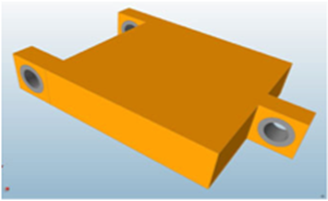
Figure 1—Bracket Design Space
(Courtesy of solidThinking)
The resulting geometry is seen in Figure 2. Note that the part contains cavities and is not manufacturable by, for example, die casting. Manufacturing constraints, for example a die draw direction, can be applied. Also, the part can be made symmetric.
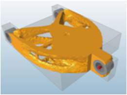
Figure 2—First-Pass Suggested Topology
(Courtesy of solidThinking)
Finally, multiple load cases can be applied, if the same part is to be used in different locations. The final result from Inspire is shown in Figure 3. This design concept is then taken into a CAD system to guide and help develop the geometry of the actual part.
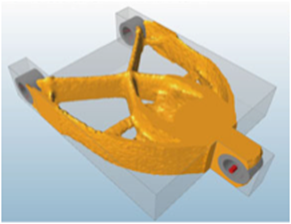
Figure 3—Final Suggested Topology
(Courtesy of solidThinking)
As noted, topology optimization is used to “discover” structural geometry that meets the product performance requirements. As such, it is most effectively used “up front”. The product development process is often represented as the systems engineering “Vee”, Figure 4. For mechanical design, detailed CAD is created at the base of the Vee. Topology optimization is best suited for use on the left side of the Vee, during system design. solidThinking’s customers who use topology optimization up front report that they now have first-time capable CAD designs, and they have eliminated cycles of redesign to meet performance requirements.
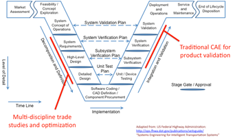
Figure 4—The Systems Engineering Vee
After the CAD design is completed, the traditional CAE simulation process is used for validation. Indeed, shape optimization (available in Altair’s OptiStruct software) may be used to fine-tune the shape.
Optimization can also be used on the right side of the Vee, though there is less flexibility since major decisions on available design space and product configurations have been made. Even so, there are opportunities to explore lighter weight designs.
Since Inspire is a stand-alone tool it does not require licenses for ancillary CAD or finite-element software. It has sufficient geometry generation capabilities for its purpose, but it is not a CAD tool. It also is not a general-purpose finite element solver. By integrating these capabilities, solidThinking has created a powerful but easy to use application.
Inspire provides unique ways to interact with and understand the structures being proposed. A slider bar can be used to add or remove material. Loads may be changed to see the effects on the structure. This is very effective for gaining an understanding of the design, and of how the structure carries the loads. These “what if” studies can be done in a short amount of time: users report being able to run variant loading conditions quickly enough on a laptop to participate in real-time design reviews. In the past such calculations might have required hours on the fastest supercomputers then available.
Topology optimization has been compared to the biological process of morphogenesis, which is how an organism develops its shape. Certainly, the structures suggested by topology optimization often have an organic, skeletal appearance. They simply look functional and efficient and are visually appealing. For this reason, topology optimization is finding applications in industrial design and architecture. Figure 5 is a stadium. The topology result is in the foreground, and the figure also shows the architect’s interpretation.
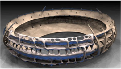
Figure 5—Stadium Structure Produced by Inspire
(Courtesy of solidThinking)
Inspire has recently been used to design supporting structures (exoskeletons) for skyscrapers, Figure 6.
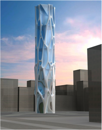
Figure 6—Exoskeleton for Skyscraper Developed in Inspire
(Courtesy of solidThinking)
CIMdata has remarked on the need to democratize simulation: Make simulation available to and usable by a much wider audience. Inspire is a tool that supports this democratization. solidThinking, with Inspire, addresses many of the obstacles to the effective application of topology optimization. These include application complexity, the need for a development team rather than a single engineer, limits imposed by software licensing, and adaptability needed so the tool can be used early in the development process.
About CIMdata
CIMdata, an independent worldwide firm, provides strategic management consulting to maximize an enterprise’s ability to design and deliver innovative products and services through the application of Product Lifecycle Management (PLM). CIMdata provides world-class knowledge, expertise, and best-practice methods on PLM. CIMdata also offers research, subscription services, publications, and education through international conferences. To learn more about CIMdata’s services, visit our website at http://www.CIMdata.com or contact CIMdata at: 3909 Research Park Drive, Ann Arbor, MI 48108, USA. Tel: +1 734.668.9922. Fax: +1 734.668.1957; or at Oogststraat 20, 6004 CV Weert, The Netherlands. Tel: +31 (0) 495.533.666.
Become a member of the CIMdata PLM Community to receive your daily PLM news and much more.
Tell us what you think of the CIMdata Newsletter. Send your feedback.
CIMdata is committed to your privacy. Your personal information will never be sold or shared outside of CIMdata without your express permission.
홈페이지
http://www.solidthinking.com/
건축 프로젝트 예제
 PMacapia_inspire_cust_story_WEB.pdf


