LUSAS Structural Analysis 

웹사이트 
http://www.lusas.com/

Case Study

Navvies Bridge

  • Outline design and Category III design check to Eurocodes of a replacement cycle / footbridge

  • Linear and nonlinear buckling analyses

  • Dynamic analyses for pedestrian and crowd loading

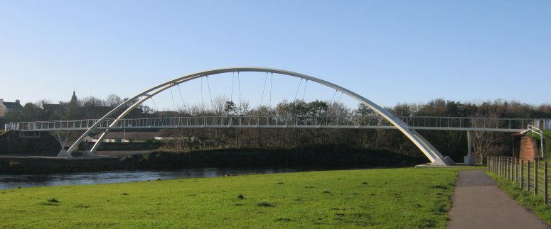
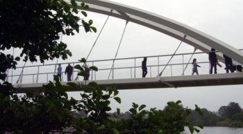
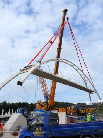
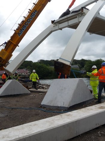
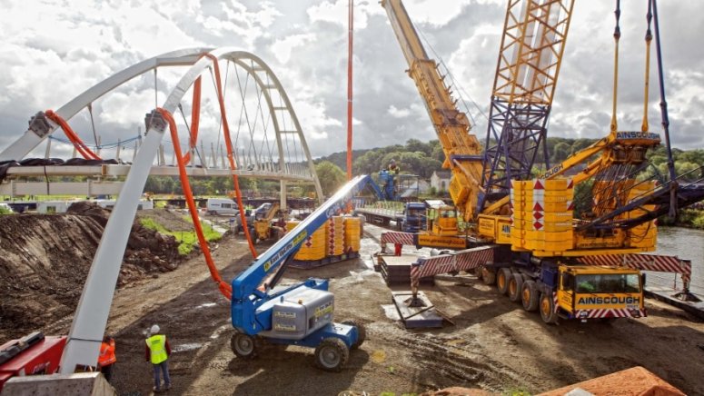
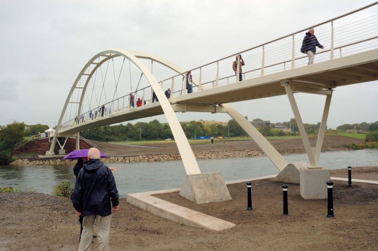
Capita Symonds was appointed by Cumbria County Council to carry out the outline design, a Category III design check and project management for the replacement Navvies Bridge in Workington, UK. The bridge comprises a twin ribbed untied bowstring arch steel superstructure, with an overall span of 84.8m, and carries cyclists and pedestrians over the River Derwent. To assist with its design and checking of the structure to the Eurocodes, Capita Symonds used LUSAS bridge analysis software.

Overview

The new bridge replaces a precast multi-span footbridge that stood at the same location, and which was partially washed away and damaged beyond repair during unprecedented flooding of the river in November 2009. The replacement arch structure spans 60m between arch springing points that are sited well above normal water levels and is better suited to withstand any potential future flooding that may occur. Funding for the new £1.7 million bridge included £375,000 from the charity Sustrans as part of a national project to provide walking and cycling routes for everyday journeys in communities across UK. At 3m in width the deck of the new bridge is almost twice as wide as the old bridge, easily accommodating its shared use. Demolition of the old bridge and the detailed design and construction of the new bridge was undertaken for the client Cumbria County Council by UK construction, infrastructure and design business Morgan Sindall. 

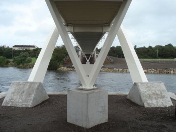
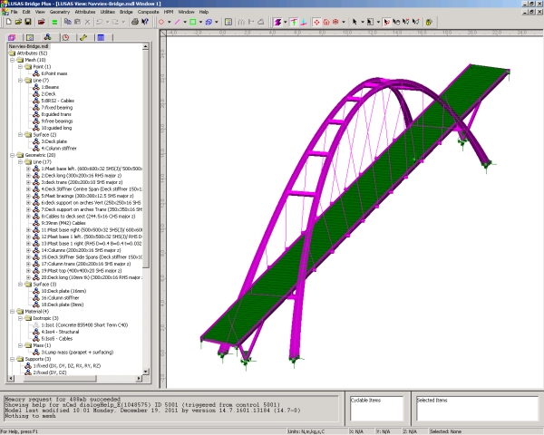
Bridge construction

The main inclined steel arch members of the bridge are of square hollow section with their principal axes rotated at 45 degrees to the main plane of each arch. The arch members taper from 600mm square at plinth level down to 500mm square at the first transverse-bracing level beneath the deck, further reduce to 400mm square at the level of the first hanger, and remain at that size for the central portion of the arch. Transverse upper bracing members separate the main arches at the central seven hanger locations. In all, nine inclined sets of 39mm diameter cables support the 300mm x 200mm x 16mm thick RHS longitudinal deck edge beams which are transversely braced at each lower cable fixing. The 16mm thick steel deck plate within the arch region is stiffened on its underside with 150mm x 12mm plates at approximately 800mm centres. Outside the arch region the deck beam and plate construction is lighter and the two 18m long back spans are supported at their mid-span positions by crossbeams sitting on V-shaped piers of 200mm square hollow section.

Navvies Bridge : Modelling in LUSAS

Modelling in LUSAS

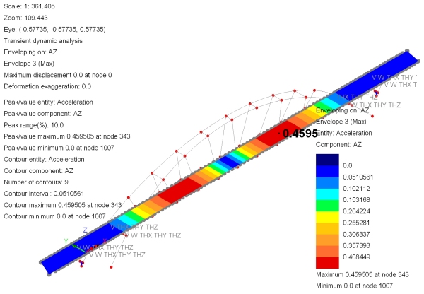
Modelling, Analysis and Results

At the outline design stage, Capita Symonds built a variety of LUSAS finite element models to undertake linear, nonlinear buckling and dynamic analysis of the structure. A linear static model allowed for preliminary section sizing and for self-weight and cable tensioning effects to be investigated. For this, a custom-created spreadsheet helped to derive the cable load factors required in order to achieve the correct deck shape. 

Antonio Di Caprio, Project Engineer at Capita Symonds said "During the conceptualisation process with the appointed architect, Mr Ron Yee of Yee Associates, we used modal and transient dynamic analyses to ensure that the response of the structure would remain within the acceptable limits given by EN 1990, using pedestrian excitations from the UK National Annex to EN1991-2." A straightforward eigenvalue analysis identified the primary range of natural frequencies and eigenmodes for the structure. Subsequent investigation of the mass participation values for each frequency (which showed the magnitude and direction of model mass participation) and the use of the LUSAS animation facility helped identify the critical vertical, horizontal and twisting modes. The fundamental modes were used for more detailed pedestrian moving-load and steady-state analysis in accordance with the requirements of the UK National Annex to BS EN 1991-2 2003 using the LUSAS Pedestrian Load Wizard. Use of this wizard simplified and automated the creation of the loadcases required to model pedestrian groups passing across a structure. Lastly, a transient dynamic crowd loading assessment required the use of load curves to represent the imposed loading with respect to time and for this damping values as suggested by the code were usedThis analysis was used to verify the comfort criteria levels by looking at the maximum vertical acceleration of the bridge deck. As a result, the ‘acceleration versus response-time’ steady-state response of the structure was obtained showing that the maximum vertical acceleration values were acceptable. Significant lateral mode frequencies were kept above the critical threshold value given in the UK National Annex to EN1991-2.

A linear buckling analysis assessed the elastic critical buckling load factor and indicated that a geometric nonlinear buckling analysis also needed to be carried out.

Animation of first eigenmode

Typical eigenmode

Typical eigenmode

Typical eigenmodes

Maximum acceleration response due to crowd loading

Category III checking

Following detailed design by Morgan Sindall, Capita Symonds was appointed by the client to carry out a Category III check of the structure which saw the existing LUSAS models being re-used, refined and re-analysed to incorporate and check the proposed design.

The 96 tonne main arch span of the new bridge was fabricated off site and assembled on the river bank before being lifted into place in August 2011. After final completion works the bridge was officially opened the following month.

Bridge lift

Bridge installed

On completion


"We used modal and transient dynamic analyses to ensure that the response of the structure would remain within the acceptable limits given by EN 1990, using pedestrian excitations from the UK National Annex to EN1991-2."

Antonio Di Caprio, Project Engineer, Capita Symonds.


Posted by Parametric Culture

RhinoVAULT


The Rhinoceros® Plug-In RhinoVAULT emerged from research on structural form finding using the Thrust Network Analysis (TNA) approach to intuitively create and explore compression-only structures.


Using reciprocal diagrams, RhinoVAULT provides an intuitive, fast funicular form-finding method, adopting the same advantages of techniques such as Graphic Statics, but offering a viable extension to fully three-dimensional problems. Our goal is to share key aspects of our research in a comprehensible and transparent setup to let you not only create beautiful shapes but also to give you an understanding of the underlying structural principles.


홈페이지

http://www.block.arch.ethz.ch/brg/tools/rhinovault

Posted by Parametric Culture

독일의 구조계산 프로그램 Dlubal Software RFEM과 RSTAB


엔지니어링이 살아야 건축도 함께 발전한다. 독일의 건축은 영국, 프랑스, 스페인, 이탈리아와랑은 다르게 건물들이 좀 딱딱해 보이는 경향이 강하다. 주로 에너지디자인에 집중하는 이유이기도 하고, 어찌보면 독일인의 건축에 대한 철학이 그러할 수도 있으리라 개인적으로 짐작한다.

영어로는 가끔 Dry한 건축이라고 농담삼아 얘기하지만, 독일의 엔지니이어링은 정말 세계최고의 수준이다. 그래서 독일의 건물들은 데게 하이테크 디자인이 많다. 독일, 아니 유럽과 세계에서 최고의 수준인 구조계산 소프트웨어를 소개한다. 물론 BIM기반의 구조계산 소프트웨어이며 REVIT과도 연동이 잘되는 편이다. 자세한 정보는 홈페이지에서 참조하자.


프로젝트 샘플


RFEM_Sobek_Flame_Towers_EN.pdf


홈페이지

https://www.dlubal.com/en/rfem-5xx.aspx

'BIM > 3. BIM Structural Design' 카테고리의 다른 글

LUSAS Structural Analysis  (0) 2015.08.10
RhinoVAULT  (0) 2015.06.28
그라소퍼 플러그인 Karamba3D  (0) 2015.06.06
신개념 스트럭쳐 디자인_Solidthinking INSPIRE  (0) 2015.05.28
Posted by Parametric Culture

그라소퍼 플러그인 Karamba3D


Karamba는 다른 여러 구조계산 프로그램과 같이 유한요소법 (Finite Element)을 통해 구조계산이 이루어집니다. 하지만, 다른 프로그램들에서 비해서 Karamba에는 여러 가지 장점들이 있습니다: 전문가가 아니더라도 쉽게 사용할 수 있고, 프로젝트의 시작점에서 엔지니어와 건축사의 필요에 맞는 작업을 쉽게 진행할 수 있으며, 비용면에서도 다른 프로그램들과 달리 저렴하게 사용하실 수 있습니다.


Karamba는 라이노 (Rhinoceros) 3D모델링 프로그램의 플러그인으로 알려진 그라소퍼 (Grasshopper)의 파라메트릭 (Parametric) 환경에 적용되는 프로그램입니다. 따라서 파라메트릭화된 기하학적 모형과 함께 쓰이며, 유한요소법 구조 계산 및 그라소퍼의 플러그인인 옥토푸스 (Octopus) 또는 갈라파고스 (Galapagos)와 함께 알고리듬을 통한 구조 최적화계산을 할수 있습니다.


상업적 목적이 아닌 무료 버전을 사용하실 수 있으며, 상업적 목적을 위한 프로버전 또는 트라이얼 버전을 이용하실 수 있습니다. 아래의 표1에서 각 라이센스별 주요 기능을 살펴보실 수 있습니다.


혹시나 과학적인 목적으로 Karamba를 사용하실 경우 아래의 논문을 참조하시길 바랍니다:

Preisinger, C. (2013), Linking Structure and Parametric Geometry. Architect Design, 83: 110-113. doi: 10.1002/ad.1564.


홈페이지:

http://www.karamba3d.com/

Posted by Parametric Culture

!!신개념 스트럭쳐 디자인_Solidthinking INSPIRE!! 


INSPIRE란 뭘까??

기존의 디자인 Volume에서 하중을 계산해 불필요한 재질을 지우고, 경량구조로 최적화해주는 구조적 디자인 툴이라고 할 수 있다. 아래의 의자 디자인을 예로보자. 아래의 예제와 같이 의자의 지탱부분인 곳에 Support설정을 주고, 사람이 앉을때 발생하는 의자부분과 등받이 부분에 Load를 설정한 뒤, 의자의 재질을 설정하고 INSIPIRE를 사용하여 계산을하면, 오른쪽 의자의 모습처럼 불필요한 재질을 없애고, 자연적인 의자의 구조적 프레임을 얻을 수 있다. 매터리얼을 없앨때에도, Percentage별로 Iteration을 볼수가 있기 때문에 구조적 디자인을 하기 좋다.


대표적 사례에 관련된 기사문

CIMdata PLM Industry Summary Online Archive

27 June 2013

CIMdata News

solidThinking Inspire Democratizes Optimization-Driven Concept Design: A CIMdata Commentary

Key takeaways:

  • Topology optimization generates efficient lightweight structures that meet performance requirements for weight, stiffness, and strength
  • Altair, the parent company of solidThinking, pioneered the commercial availability of topology optimization with OptiStruct
  • solidThinking Inspire is a purpose-built topology optimization tool that can be used by design engineers up front in the product development process
  • Customers report that topology optimization results in first-time capable designs and eliminates iterative redesigns to meet performance requirements
  • solidThinking Inspire is finding applications in industries beyond automotive and aerospace, including architecture and industrial design
  • The organic shapes generated with this technology are functional and often aesthetically appealing

As the revolution in digital product definition continues, strong forces are seeking to democratize the tools that are employed, to make them easier to use and accessible to a wider audience. Particularly as simulation drives into the early part of the product development process, to help select product concepts and to define product architecture, the tools must be simpler, faster, and more capable to support critical product decisions that cross multiple disciplines.

Leading thinkers focus on the idea that the geometry of a product design should be a result of the design process, not a starting point. They envision a systems engineering approach, where the physical design is derived or synthesized from its performance and other requirements. In this paradigm, geometry is fully a part of the design discovery process.

Topology optimization is one way to “discover” structural geometry that is optimized to meet a prescribed set of performance targets while satisfying constraints like minimum weight or maximum stiffness.

Altair pioneered the commercial availability of topology optimization with OptiStruct in the early 1990s. Since then, topology optimization has become routine in industries where efficient structures are important, like aerospace and automotive. The inclusion of manufacturing and other constraints improved the applicability of the technique, but it remained something that required expert knowledge of both FEA and CAD to utilize.

Seeking to broaden the market for topology optimization, solidThinking (an Altair company) has now embedded the technology in a stand-alone, purpose-built tool, solidThinking Inspire. Inspire removes the need for an expert understanding of FEA and CAD to apply topology optimization. Further, it fits the need to apply topology optimization at the concept stage, ahead of detailed CAD design and the usual simulation process for product validation.

In creating Inspire, solidThinking displays innovation and a deep understanding of the design and product development process. Topology optimization is best applied during the product ideation stage, while there is still freedom to decide on system packaging and overall product layout; where concepts must be quickly explored, and there is not time to engage a team including CAE and CAD specialists to do an optimization study. The expert engineers engaged in defining product architecture are usually not skilled in applying CAE or CAD tools. Inspire is a tool for these design-responsible expert engineers.

Topology optimization is a remarkable technology. It is used to generate efficient structures that carry or transmit prescribed loads. The user defines the volume that the structure may occupy, and its loads and attachment points. The solution process involves a finite element model in which the density of the material is essentially a variable. Material is removed from regions that are less essential for carrying the loads. Optimization techniques are used to develop structural geometry that meets requirements such as minimum weight or maximum stiffness.

Commercial software for topology optimization has been available for two decades, but was constrained by many practical difficulties. It was only usable by FEA experts, the resulting structures were difficult to realize in standard MCAD packages, and were often not manufacturable by traditional methods for injection molding, stamping, or die casting. Thus, while success was achieved in creating designs for essentially 2D structures like spars, trusses and mounting brackets, the true potential of topology optimization was not being realized. As already noted, a topology optimization project typically required a team including an engineer with product knowledge, an FEA specialist and a CAD specialist.

The topology optimization process is as follows: In Figure 1, the design space for a bracket is defined. Loads are applied, and constraints or objectives for stiffness or weight are set.

Figure 1—Bracket Design Space
(Courtesy of solidThinking)

The resulting geometry is seen in Figure 2. Note that the part contains cavities and is not manufacturable by, for example, die casting. Manufacturing constraints, for example a die draw direction, can be applied. Also, the part can be made symmetric.

Figure 2—First-Pass Suggested Topology
(Courtesy of solidThinking)

Finally, multiple load cases can be applied, if the same part is to be used in different locations. The final result from Inspire is shown in Figure 3. This design concept is then taken into a CAD system to guide and help develop the geometry of the actual part.

Figure 3—Final Suggested Topology
(Courtesy of solidThinking)

As noted, topology optimization is used to “discover” structural geometry that meets the product performance requirements. As such, it is most effectively used “up front”. The product development process is often represented as the systems engineering “Vee”, Figure 4. For mechanical design, detailed CAD is created at the base of the Vee. Topology optimization is best suited for use on the left side of the Vee, during system design. solidThinking’s customers who use topology optimization up front report that they now have first-time capable CAD designs, and they have eliminated cycles of redesign to meet performance requirements.

Figure 4—The Systems Engineering Vee

After the CAD design is completed, the traditional CAE simulation process is used for validation. Indeed, shape optimization (available in Altair’s OptiStruct software) may be used to fine-tune the shape.

Optimization can also be used on the right side of the Vee, though there is less flexibility since major decisions on available design space and product configurations have been made. Even so, there are opportunities to explore lighter weight designs.

Since Inspire is a stand-alone tool it does not require licenses for ancillary CAD or finite-element software. It has sufficient geometry generation capabilities for its purpose, but it is not a CAD tool. It also is not a general-purpose finite element solver. By integrating these capabilities, solidThinking has created a powerful but easy to use application.

Inspire provides unique ways to interact with and understand the structures being proposed. A slider bar can be used to add or remove material. Loads may be changed to see the effects on the structure. This is very effective for gaining an understanding of the design, and of how the structure carries the loads. These “what if” studies can be done in a short amount of time: users report being able to run variant loading conditions quickly enough on a laptop to participate in real-time design reviews. In the past such calculations might have required hours on the fastest supercomputers then available.

Topology optimization has been compared to the biological process of morphogenesis, which is how an organism develops its shape. Certainly, the structures suggested by topology optimization often have an organic, skeletal appearance. They simply look functional and efficient and are visually appealing. For this reason, topology optimization is finding applications in industrial design and architecture. Figure 5 is a stadium. The topology result is in the foreground, and the figure also shows the architect’s interpretation.

Figure 5—Stadium Structure Produced by Inspire
(Courtesy of solidThinking)

Inspire has recently been used to design supporting structures (exoskeletons) for skyscrapers, Figure 6.

Figure 6—Exoskeleton for Skyscraper Developed in Inspire
(Courtesy of solidThinking)

CIMdata has remarked on the need to democratize simulation: Make simulation available to and usable by a much wider audience. Inspire is a tool that supports this democratization. solidThinking, with Inspire, addresses many of the obstacles to the effective application of topology optimization. These include application complexity, the need for a development team rather than a single engineer, limits imposed by software licensing, and adaptability needed so the tool can be used early in the development process.

About CIMdata

CIMdata, an independent worldwide firm, provides strategic management consulting to maximize an enterprise’s ability to design and deliver innovative products and services through the application of Product Lifecycle Management (PLM). CIMdata provides world-class knowledge, expertise, and best-practice methods on PLM. CIMdata also offers research, subscription services, publications, and education through international conferences. To learn more about CIMdata’s services, visit our website at http://www.CIMdata.com or contact CIMdata at: 3909 Research Park Drive, Ann Arbor, MI 48108, USA. Tel: +1 734.668.9922. Fax: +1 734.668.1957; or at Oogststraat 20, 6004 CV Weert, The Netherlands. Tel: +31 (0) 495.533.666.

Become a member of the CIMdata PLM Community to receive your daily PLM news and much more.

Tell us what you think of the CIMdata Newsletter. Send your feedback.

CIMdata is committed to your privacy. Your personal information will never be sold or shared outside of CIMdata without your express permission.


홈페이지

http://www.solidthinking.com/


건축 프로젝트 예제


PMacapia_inspire_cust_story_WEB.pdf


'BIM > 3. BIM Structural Design' 카테고리의 다른 글

LUSAS Structural Analysis  (0) 2015.08.10
RhinoVAULT  (0) 2015.06.28
독일의 구조계산 프로그램 Dlubal Software RFEM과 RSTAB  (0) 2015.06.07
그라소퍼 플러그인 Karamba3D  (0) 2015.06.06
Posted by Parametric Culture